Introduction: Finally Starting My First Turbine Project
Welcome back! After what feels like an eternity, it’s finally time to start building my first turbine jet – the FTL Lancer. For those who missed the unboxing back in March, it’s been quite a journey. I received this model nine months ago, and shamefully, it’s been sitting on the shelf ever since. I’ve had countless comments on Facebook asking, “Matt, when are you going to build your jets?” Well, the wait is over. Life has been rather hectic this year, which really impacted my workshop time, but enough excuses – let’s get building.
The Background Story: How I Chose This Model
I purchased this jet after seeing FTL for the first time at Jet Power in Germany in 2024. I got to know Ben really well and even conducted an interview with him. After learning more about the company, I thought, why not give it a go?
However, I need to make a confession. When you’re at these shows surrounded by aircraft of all sizes, you experience what we call the “show effect” – big planes don’t look particularly large when there are absolutely massive jets nearby. FTL offers two sizes of the Lancer, and I decided to go for the 2.8-metre version, which is the larger one. When it arrived and I unpacked it, I thought, “This is rather big for a very first turbine.” That might have been mistake number one.
Confession number two: I’ve never built a turbine before, and I’ve never even flown one. So this is going to be quite interesting. I don’t really know where to start, so I might have to call in one of my mates to help me along the way.
The Equipment List
Fortunately, I’ve got everything needed for this build:
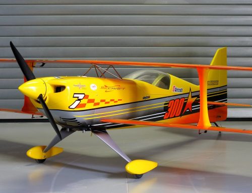
- The FTL Lancer model with custom paint scheme
- Futaba and advanced radio gear
- Theta servos (combination of 398 and 988 servos)
- King Tech G5 210 turbine
- Various bits and pieces from Paul at Nexus Models, including the fuel caddy
All the gear and absolutely no idea – as per normal! But let’s crack on with it.
Starting with the Control Surfaces
Horizontal Stabilisers and Rudder
I’m starting with what I do know – bolting in servos. All servos will be Theta servos, which I’ve used in some of my 3D planes before and absolutely love. The horizontal stabilisers will have 398 servos, and in total, this model requires 12 servos, which feels like quite a lot.
The custom paint scheme FTL created for me looks absolutely gorgeous. The process for the stabilisers is straightforward: ensuring the holes are big enough, gluing them in with cyanoacrylate, and then hooking everything up.
I’m not using the plastic servo heads that come with the Theta servos. Instead, I’ve swapped them out for metal ones – also made by Theta – which are a bit longer and have an M3 thread in the top. I’m using M3 bolts with M3 nuts on the back, all locked tight, and connecting everything with Craft 3mm ball links.
Important note: I haven’t used the rubber grommets that typically come with servos, which feels really weird for me. However, it’s not recommended to use them on this model. If you do use them, your alignment for the servo head and the pre-cut hole would be out, as the servo would sit further away and cause the linkage to hit at an angle. So I’ve gone straight in, pre-drilled the holes, added a bit of cyanoacrylate, and screwed the servos in.
The rudder followed exactly the same process – servo underneath, slightly enlarged holes, same linkage setup. These first three parts were pretty easy to be honest, just standard stuff.
Tackling the Wings
Next up were the wings, which are considerably more complex. They’ve got ailerons, flaps, and of course, the retracts as well.
Wing Construction Details
The wings are absolutely gorgeous, and it’s worth noting that you can’t actually see any of the control surfaces from the outside because everything is internal. There’s a hatch where one of the servos sits on a bracket to control the aileron. Further down, there’s where the retract goes, and the flap servo is already accessible through another panel.
The Installation Process
What I thought would be straightforward – just chuck a couple of servos in and screw a retract in – turned out to be quite a job. It probably took me the better part of an afternoon to complete one wing, though the second should be easier now I know exactly what to do.
The aileron servo: This sits on the bracket with the internal rod system, which works really nicely. I had to move the flap out of the way to access the end of the aileron to attach the other end of the rod. What wasn’t straightforward was running the wire from that servo through to the end of the wing. I had to use a bit of piano wire to feed it through, which took about half an hour.
The flap servo: This one caused me a bit of trouble. Getting the servo in was straightforward, but working out the correct rod setup took time. I had the wrong size head on initially, but once sorted, the rod went in and remained accessible.
The retract: This was actually pretty straightforward, though there are quite a lot of parts. You have a segment which attaches to the retract itself, a door which opens and stays connected with a rod, and at the front hatch, there’s a servo which opens that hatch.
Wiring and Connectors
To tidy everything up, I’ve added two PowerBox connectors on each wing:
- Three-in-one connector: For all three servos (aileron servo, flap servo, and the door servo)
- Two-in-one connector: For the two wires from the retract (one for the brake and one to make the wheel retract itself – these only carry power, not signal)
Retract Sequencing
The retract sequence works brilliantly and is all controlled by one switch. When retracting, the door opens first, the wheel comes up, and the flap closes afterwards. When extending, the door opens, the wheel comes down, and the door closes. This is all controlled by a box supplied by FTL, which is really easy to use. You just set up the modes, and it works perfectly.
After completing both wings, I was really pleased with the result. There might be a little bit of final adjustment once everything’s on the model, but right now, it’s all working – flaps, ailerons, the retract servos, and the retracts themselves.
Moving to the Fuselage
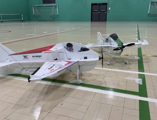
With the wings complete, it was time to move into the studio where there’s more space to work on the fuselage. I have to admit, I’d forgotten two things: firstly, how big this jet is at 2.8 metres, and secondly, just how good this colour scheme looks. Even with a layer of dust from sitting on the shelf, it’s stunning.
Fuselage Overview
Inside the fuselage, there’s a hole and linkages for a servo which will control the front door, and the retract will sit further back in the threaded holes. There’s a section where I’ll probably mount most of the gear, the main tube for the wing, and of course, the turbine will be sitting at the back.
The fuselage features thumb screws – five on each side – because the rear end completely separates for transportation.
Nose Retract Installation
What I thought would take about 10 minutes ended up taking 2 hours. Getting the retract wheel in and setting up the door should have been simple – we’d already done it on the wings. The problem was that the wheel was going down before the door was opening, which would obviously cause issues.
I went through all the different settings on the controller trying to get it working, and nothing would work. Eventually, I posted on Facebook, received loads of helpful comments, and somebody finally said to just change the polarity around on the nose leg retract itself. I was a bit shocked, but it worked perfectly.
The solution: I had to plug the connector in the opposite way around – positive to negative, negative to positive – which changed the direction of the motor in the retract. Now the door opens, the wheel goes down nicely, and the door closes properly.
Unfortunately, in the process, I put a small crack in the door at the front. I’ve sealed it with cyanoacrylate, and luckily it didn’t go all the way through, so it should be absolutely fine.
Calling in Expert Help
I got a bit stuck when it came to sorting out the fuel tank and fitting the turbine. Since I’ve never done one of these before, I decided to call in an expert. Well, I tried to find an expert, but they were all busy, so I called Andy instead! He was the last resort, but I greatly appreciated his help.
The Installation Plan
Our plan was to:
- Install the thrust tube and turbine, working from back to front
- Site the fuel tank once we knew where all the tubing would run
- Work out the plumbing for the fuel tank vent and bung
- Install the UAT (Universal Accessory Terminal)
Turbine Installation Process
The turbine installation was more complicated than I initially thought, and I’m glad Andy was there to guide the process. Here’s what we did:
Thrust tube alignment: We started by shimming the end of the thrust tube to ensure the gap around the outside where the nozzle sits was equal all the way around.
Centre line issue: We discovered that the centre line of the turbine didn’t match up with the centre line of the thrust tube where the brackets are. The two bits of wood where the brackets sit on the thrust tube aren’t at the centre of the thrust tube. It took us a while to work out what the issue was.
The solution: We needed to shim out 13mm, so we used some Extreme Flight shims from engine mounts – a 12mm shim plus a washer. Now the centre line of the turbine mount matches the centre line of the thrust tube perfectly.
Nozzle positioning: The King Tech G5 210 instructions were a little light on where to position the nozzle and how far to insert it into the bell mouth. We went with the tried and tested method of 25mm from the end of the thrust tube to the end of the nozzle. The King Tech G5 210 has an incredibly long nozzle, so it sits a bit further out from the end of the thrust tube than Andy was used to.
The process involved a lot of measuring – measure, measure, measure, measure, drill – but the end result looks excellent. Looking down the thrust tube, the alignment appears perfect.
We also attached two bits of fuel tube to the turbine mounted on G10 mounting plates. One is the actual fuel input for the turbine, and the other is marked “start” – apparently the pump uses different tubes for starting the engine and running it.
Fuel Tank Preparation
After Andy went home (and after a month had passed due to life getting in the way, including a trip to Dubai for the MAD show), I continued with the fuel tank preparation.
Tank Modifications
I was slightly surprised that you have to drill the holes yourself in the jet world, but that’s apparently standard. We created:
- A hole for the main bung
- A hole through the top for the vent
We used high-temperature silicone around both holes to create tight seals. Before installing it, I’ll rinse out the tank with alcohol to remove any dust and debris. Some people apparently put a very thin layer of epoxy inside their tank and swirl it around to coat the inside, but I’m not going to do that – I’ll use it as is and hopefully won’t regret it later.
Fuel System Components
I made up the clunk and bung assembly using parts supplied by Paul from Nexus Models. Paul spent about an hour on the phone with me going through what might seem like basic stuff to experienced jet builders, but it was incredibly helpful for a newbie like me.
The quick-release adapters are particularly nice – the top piece can twist around to different angles and comes out easily. Paul recommended a high-flow fuel tank bulkhead insert and a fuel tank vent insert, along with various other bits that I’ll use as we continue fitting everything to the model.
What’s Next
The next steps involve installing the tank in the model, laying out all the components including the UAT and electronics, and working out where everything will go. I’m really excited to continue with this build.
I’m pausing this video here as it’s already half an hour in length. I apologise to those of you who have been waiting for me to start building this FTL Lancer, but the good news is that part two will be out very soon. I’ve already continued with the model, and that second video is almost ready. Much of the model is now actually complete, and I’m in the final stages, which I’m hoping to finish in the next couple of weeks.
Part two should be available within two to three weeks of this video. I hope to see you then!

[…] build! After sitting on the shelf for nearly a full year, this model is finally coming together. In part one, we assembled the wings, installed the retracts and servos, completed the horizontal stabiliser and […]