Back to the Workshop: Component Layout and Planning
Welcome back to part two of the FTL Lancer turbine build! After sitting on the shelf for nearly a full year, this model is finally coming together. In part one, we assembled the wings, installed the retracts and servos, completed the horizontal stabiliser and rudder, mounted the turbine, and assembled the fuel tank. Now it’s time to tackle the electronics, custom wiring, nose gear, and get this turbine fired up.
The goal is to have this model flight-ready within the next month or so, as soon as the weather improves here in the UK. Let’s dive in!
Component Placement Strategy
First things first: laying out the components in the fuselage. Now, there’s probably no single “right” way to do this, and I’m sure experienced jet builders might have different approaches. If you’re a jet expert, please share your wisdom in the comments below!
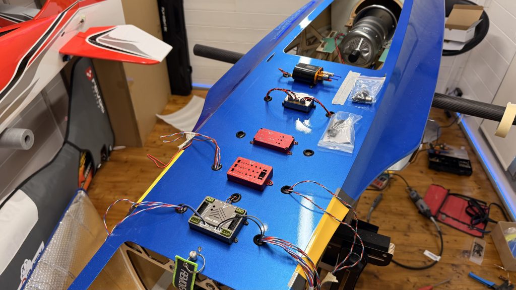
Here’s my current layout from front to back:
- Front section: One receiver mounted up front
- Mid-forward: Four batteries total—two on each side plate
- Centre: UAT (Unpowered Air Turbine) positioned on a tray, facing the fuel tank
- Below centre: Second receiver in this area
- Fuel tank: Sits in its frame holder with the valve facing towards the UAT
Understanding the UAT Configuration
The UAT has three connections on the front, and positioning is critical:
- One line goes directly to the tank
- One runs towards the turbine
- One is for fuelling up
I’m angling the top valve strategically so the magnetic vent sits somewhere accessible when I need to pull it out from underneath before fuelling. The fuel valve will be positioned where I can easily unplug it, connect the fuel line for refuelling, then reattach and lock it off.
The fuel system flow goes: fuel valve → fuel filter → pump → turbine (on the G5, which has two inlets). There’s also a fuel cutoff positioned along this route for safety.
Additional Components
Moving back to the top of the fuselage:
- ECU (Engine Control Unit): Positioned on top, next to the pump
- GSU screen: The ground support unit screen will be mounted with double-sided tape (no permanent mounting holes) so I can remove it later once everything’s properly set up
- Retract and brake controllers: Running down the centre line, both operating off a single 2S battery via a Y-lead
- Pump: Running off a 3S battery, positioned slightly off-centre to accommodate the mounting holes
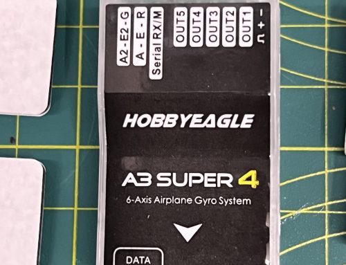
- SF20 Pro: The Smooth Flight system (sponsored equipment) will have its own dedicated setup video later
The Wiring Marathon Begins
With components positioned, it was time to start the actual wiring—and I’ll be honest, this took considerably longer than anticipated. What I thought would be a few hours turned into multiple days of work.
Wing Connections
The wings required Power Box 2-in-1 and 3-in-1 connectors—one set for the servos and another for the retract mechanism and brakes. I had to run corresponding connectors through the fuselage, which meant:
- Extending wires (not ideal, but necessary given the connector wire lengths)
- Creating custom ends with heat shrink tubing
- Threading everything through protective sleeving (what I call “snake skin shielding”)
- Routing wires underneath the fuselage to come up near the Smooth Flight and retract controller
This process had to be done for both sides, resulting in ten wires coming through to the front—five from each wing (two for retracts/brakes, three for servos).
Tail Section Wiring
The rear fuselage presented its own challenges. I used Power Box 1-in-1 connectors with nice locking plates that prevent them from falling back down. These were fitted to:
- The rudder
- Both sides of the horizontal stabiliser
All three tail wires run through to a single 3-in-1 Power Box connector at the front. The tricky bit? I had to remove the thrust tube from the back of the fuselage to thread these wires through, and they needed to be in heat-resistant casing, cable-tied well clear of where the thrust tube sits (as it gets extremely hot).
The fuselage splits in half as well, so I incorporated connectors that allow me to separate the sections whilst maintaining all the electrical connections.
Wire Management Challenges
After approximately four hours of initial wiring work, I had reached a point where thirteen sets of wires were positioned at the front of the fuselage. The routing went like this:
- Right side: Three wing servo wires, two gear wires, all running down the right-hand side of the fuselage
- Left side: Same configuration, plus the three tail servo wires
- Turbine wiring: All turbine-related wires threaded through and positioned
The next step was mounting the Smooth Flight unit, brake controller, and retract controller in their final positions, then drilling proper grommeted holes for all the wires to pass through tidily.
A Costly Mistake (and Learning Moment)
I need to make a confession: I made a mistake during this build. After creating all the custom wiring looms and plugging everything into the Smooth Flight, I discovered one of the flaps wasn’t working. The servo had no power.
I spent considerable time troubleshooting, even removing the entire left-side wiring loom from the fuselage, convinced the issue was there. In reality? The connector in the wing was simply the wrong way round. The servo wires are black with a white line on one side (the signal wire), and I’d connected it incorrectly. A simple brain fade, but it cost me hours of work.
The silver lining? It forced me to go back through everything and tidy up the installation more thoroughly than I might have otherwise.
Another Quick Correction
I’d been calling the engine control unit the “GSU” (Ground Support Unit), which is incorrect. The ECU is the Engine Control Unit—essentially like having an ECU in a car. The screen itself is the Ground Support Unit. Being new to turbines, these terminology mistakes happen, but I wanted to correct it for anyone following along.
System Testing and Configuration
With the left wing properly wired, I could finally start testing systems. Using my Futaba T26 transmitter with a newly configured model, I plugged in both receivers to the Smooth Flight 20 Pro and powered everything up.
Initial System Checks
The results were encouraging:
- Both elevators working correctly
- Rudder responding properly
- Left aileron functioning
- Left flap operational
- Gear doors opening and closing in sequence
- All three retract units deploying and retracting correctly
I hadn’t done any advanced setup yet—no flight conditions, rates, or exponential settings. The goal at this stage was simply to verify everything moved in the correct direction.
Retract Controller Frustrations
The JP retract controller caused some head-scratching moments. With just the left wing attached, everything worked perfectly. Remove the left wing, attach the right wing, and the gear doors wouldn’t function properly.
After consulting the manual, I discovered the issue: the servo reverse setting works in conjunction with the sequence setting. If the servo is mounted one way, the sequence must match. I’d configured it incorrectly, resulting in doors that simply wouldn’t move.
Several people commented on the first video suggesting I replace the JP controllers, as they’re not particularly popular in the jet community. Whilst I’m trying to use all the components that came with the FTL model as intended, I’ll admit the jury’s still out on whether these controllers will stay long-term.
The Canopy Catastrophe
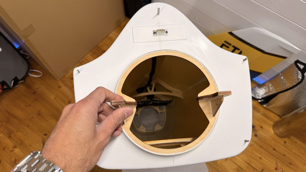
With the model finally assembled outside for the first time, I thought it would be the perfect opportunity to fit the canopy and take some photographs for social media. That’s when I discovered a rather embarrassing mistake: the canopy no longer fits.
The canopy has two support structures underneath—one at the front and one at the back. The rear support now hits my newly mounted fuel pump. This was entirely my fault for not checking clearances properly. In my defence, I’d been working on this model over multiple days and weeks, and it simply didn’t occur to me to verify the rear clearance (though I had checked the front!).
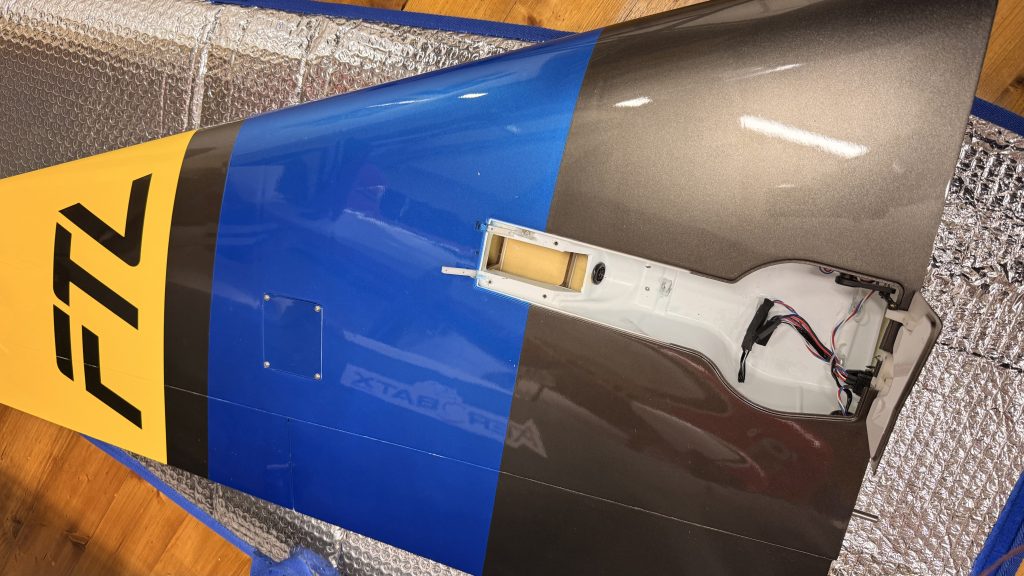
Problem Solved (Sort Of)
The solution was to relocate the pump forward, towards the ECU. This meant drilling a new mounting hole, leaving me with an extra hole I didn’t particularly need. It’s not the tidiest solution, but the canopy now fits with proper clearance, and that’s what matters.
This is a good reminder to always check canopy clearances before permanently mounting components—a lesson I won’t forget!
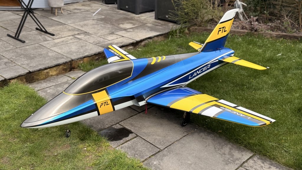
First Full Assembly
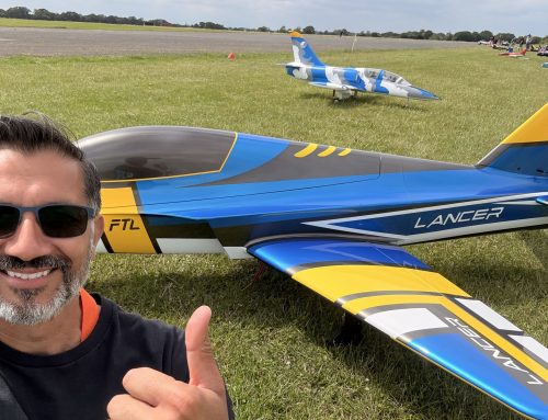
Despite the canopy hiccup, seeing the Lancer sitting on its wheels for the first time was genuinely exciting. This is when the model really shows its true size—and I’ll be the first to admit, it’s possibly a bit too large for a first turbine model. But we’re here now, and it looks absolutely magnificent.
The retracts all function correctly, with gear doors operating in proper sequence. There’s a minor adjustment needed on one door that isn’t closing completely flush, but that can be fine-tuned via the controller or servo settings later.
Battery Configuration
The power system uses multiple batteries for redundancy and proper power distribution:
- Two batteries for the Smooth Flight 20 Pro (dual redundancy)
- One 2S battery powering both the retract controller and brake controller via Y-lead
- One 3S battery for the fuel pump
- One battery for the ECU
All batteries are securely mounted on plates to either side of the centre fuselage—much tidier than my initial test configuration!
Final Systems and Fuel Installation
We’re now at about 99% completion. The wiring is finished and tidied (to a reasonable standard—I’m sure some of you could do better, but I’m satisfied with where we’ve got to). The batteries are properly secured, and the fuel system is almost complete.
Fuel System Components
The fuel valve is positioned for easy access—simply undo it, slide it over, fuel through the connection, and pop it back in place. The filter is installed in line, followed by the pump feeding the turbine.
One item on my list: I need to add a weight to the nose. During testing, I noticed the model wants to sit back on its tail, which isn’t ideal. A simple nose weight will sort this out before the first flight.
What’s Next?
We’re incredibly close now. The remaining tasks include:
- Final brake system testing and adjustment
- Installing the nose weight for proper balance
- Completing the fuel system connections
- Initial turbine start-up and testing
- Fine-tuning all the retract sequences
- Detailed Smooth Flight 20 Pro configuration (separate video coming)
This build has taken far longer than I estimated—particularly the wiring phase, which consumed multiple full days of work. But we’re finally at the stage where the model is coming together, and I couldn’t be more pleased with the progress.
If you’re a jet expert or have experience with turbine models, I’d love to hear your thoughts and suggestions in the comments below. What would you have done differently? Any tips for first-time turbine pilots?
Stay tuned for the final part where we’ll fire up this beast and get it ready for its maiden flight!